
Design and Construction of Technology Systems for a Large-Scale Complex of 3 Swimming Pools

1. Operating principle of the three independent filtration systems
The core of this engineering solution is that each pool has its own filtration system, circulation pumps and completely separate piping routes. This ensures that when one pool needs cleaning, maintenance or water quality adjustment, the other two pools keep running continuously without disturbance.
| Parameter / Characteristic | Competition pool | Training pool | Children’s pool |
|---|---|---|---|
| Scale / Flow rate | Largest in the complex | Medium | Area of approximately 84.4 m² |
| Balancing tank | Dedicated tank on the 1st floor (volume ~189 m³) | Dedicated tank on the 1st floor (volume ~29.5 m³) | Uses the volume of the overflow gutter as the balancing tank |
| Circulation flow diagram | Pool ➔ Overflow gutter ➔ Balancing tank ➔ Pump ➔ Filter tank ➔ Treatment ➔ Return inlet | Pool ➔ Overflow gutter ➔ Balancing tank ➔ Pump ➔ Filter tank ➔ Treatment ➔ Return inlet | Pool ➔ Overflow gutter ➔ Pump ➔ Filter tank ➔ Treatment ➔ Return inlet |
| Main piping | Multiple uPVC D220 routes for overflow collection, suction and water return | Separate bottom collection, balancing tank suction and water return routes | Independent suction, return and treatment lines |
2. Applying the BIM Revit 3D model in technology design
With a total of 13 pressure filter tanks and a large piping network running from the 1st floor up to the pools, modeling in Autodesk Revit is essential for controlling space.
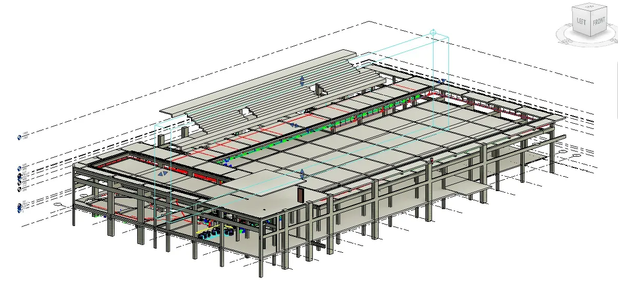
The BIM Revit 3D model helps engineers handle the following issues at the same time:
- Accurately locating the 13 filter tanks, circulation pump groups and maintenance space.
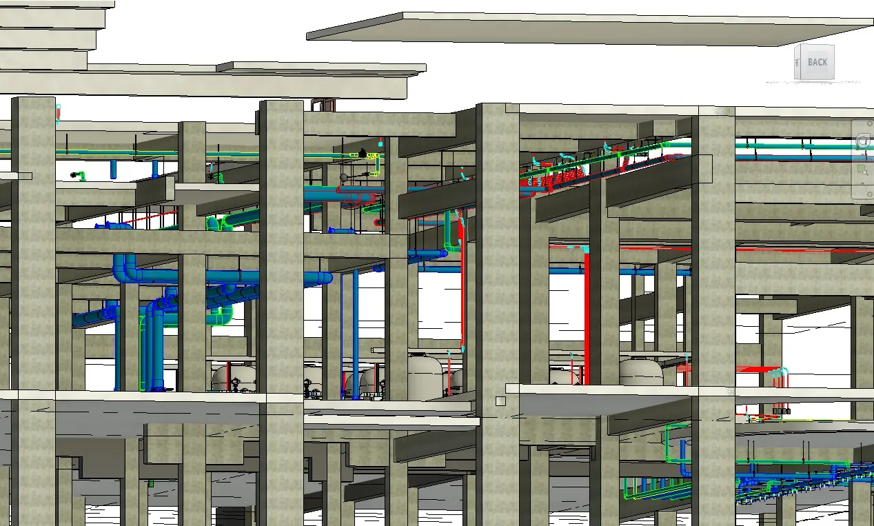
- Calculating the elevations and slopes of the uPVC D220, D114, D90, D60, D49 and D34 pipe routes.
- Resolving clashes between technology pipe routes, embedded electrical conduits and floor beam structures.
- Extracting shop drawings, wall penetration details and pipe support systems (single hangers, double-rod hangers, floor supports).
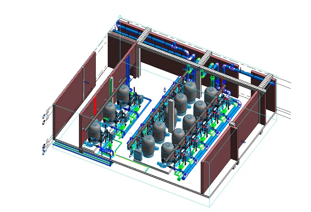
Model of 13 filter tanks divided among the 3 pool systems
3. Plant room automation with a PLC control system and motorized valves
Each of the 13 filter tanks is fitted with a set of motorized angle valves connected directly to the PLC programmable control cabinet. The system automatically switches operating modes following a safe logic sequence:
FILTER TANK STATE-SWITCHING LOGIC (PLC)
1. Stop the corresponding circulation pump
2. Trigger the motorized valves to switch state (Filter / Backwash / Rinse / Closed)
3. Feedback signal confirms the valves are fully closed/open
4. Restart the circulation pump
The main operating modes of the filter tank:
- FILTER: Normal circulation filtration mode.
- BACKWASH: Backwash mode that cleans the filter media layer.
- RINSE: Forward rinse mode that settles the media after backwashing.
- CLOSED: Fully isolates the filter tank when maintenance or repair is needed.
4. System construction and commissioning process
Because most of the piping and technical details will be embedded in concrete or beneath finishing layers, the construction process requires strict adherence to each stage.
Construction and commissioning process
-
1
Embedded structural works
Install sleeves, wall penetration pipes, bottom suction hoods, return inlets, HDPE D20 conduits embedded in the floor for underwater lights, and carry out waterproofing.
-
2
Plant room piping and equipment installation
Build the technology piping network (up to D220), and install the 13 filter tanks, circulation pumps, motorized valves, PLC electrical cabinet and chemical dosing system.
-
3
Hydraulic testing and independent trial runs
Pressure and leak testing of the entire pipe network. Commission each system separately: Pump ➔ Filter tank ➔ PLC motorized valve ➔ Chemicals ➔ Underwater lights.
-
4
Flow balancing and handover training
Balance the flow rates of overflow gutter collection, bottom collection and return inlets. Train operators on isolating each equipment group and handling incidents.
Important considerations during implementation
- Waterproofing pipe collars: Wall penetrations and HDPE D20 conduits embedded in the floor for lighting must be waterproofed in step with the work from the concrete pouring stage.
- Hydraulic safety: The delay time when switching motorized valve states in the PLC program must be long enough for the pump to stop completely, avoiding water hammer that could break uPVC pipes.
- Reinforcing large pipes: The uPVC D220 pipe routes require beam hangers and floor supports positioned precisely to bear the load and prevent the pipes from sagging when full of water.
Conclusion
The design and construction solution for a three-pool complex, with three independent technology filtration systems, BIM Revit 3D and PLC automation control, delivers optimal, safe operation that is easy to maintain. Strict adherence to the construction process, from embedded structural works through to commissioning, helps the facility meet the highest quality standards.


Other Technical Articles
 Advanced
Design and Construction of an Automatic Irrigation System for a Large-Scale Eco-Urban Area
Designing and building an automatic irrigation system for a large-scale eco-urban area of 1.83 million m² demands sophisticated...
Read Article Advanced
Design and Construction of a Large-Scale Performance Pool Technology System Using BIM Revit
Design and construction of a large-scale performance pool technology system using BIM Revit is one of the water...
Read Article Advanced
BIM Revit Design and Construction of a District 7 Hospital Wastewater Treatment System – 300 m³/day
This 300 m³/day hospital wastewater treatment plant was delivered by NTS Engineering on a turnkey basis, from process...
Read Article