
BIM Revit Design and Construction of a District 7 Hospital Wastewater Treatment System – 300 m³/day
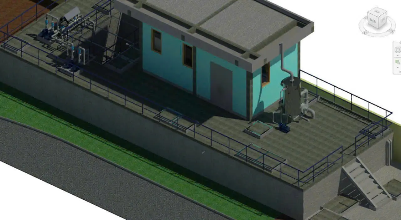
1. Technology overview and treatment process of a 300 m³/day hospital wastewater plant
Unlike small-scale systems, a 300 m³/day hospital wastewater treatment plant uses a continuous multi-stage biological treatment line combined with MBR membrane technology, blower systems, pumps, chemicals and an automatic control cabinet.

According to the process flow diagram, the wastewater passes in sequence through: Collection tank → Primary settling → Equalization tank → Anaerobic tank → Anoxic tank → Aerobic tank → MBR membrane tank → Disinfection before discharge to the receiving water body. Alongside the main water stream, the sludge, air and chemical lines operate simultaneously.
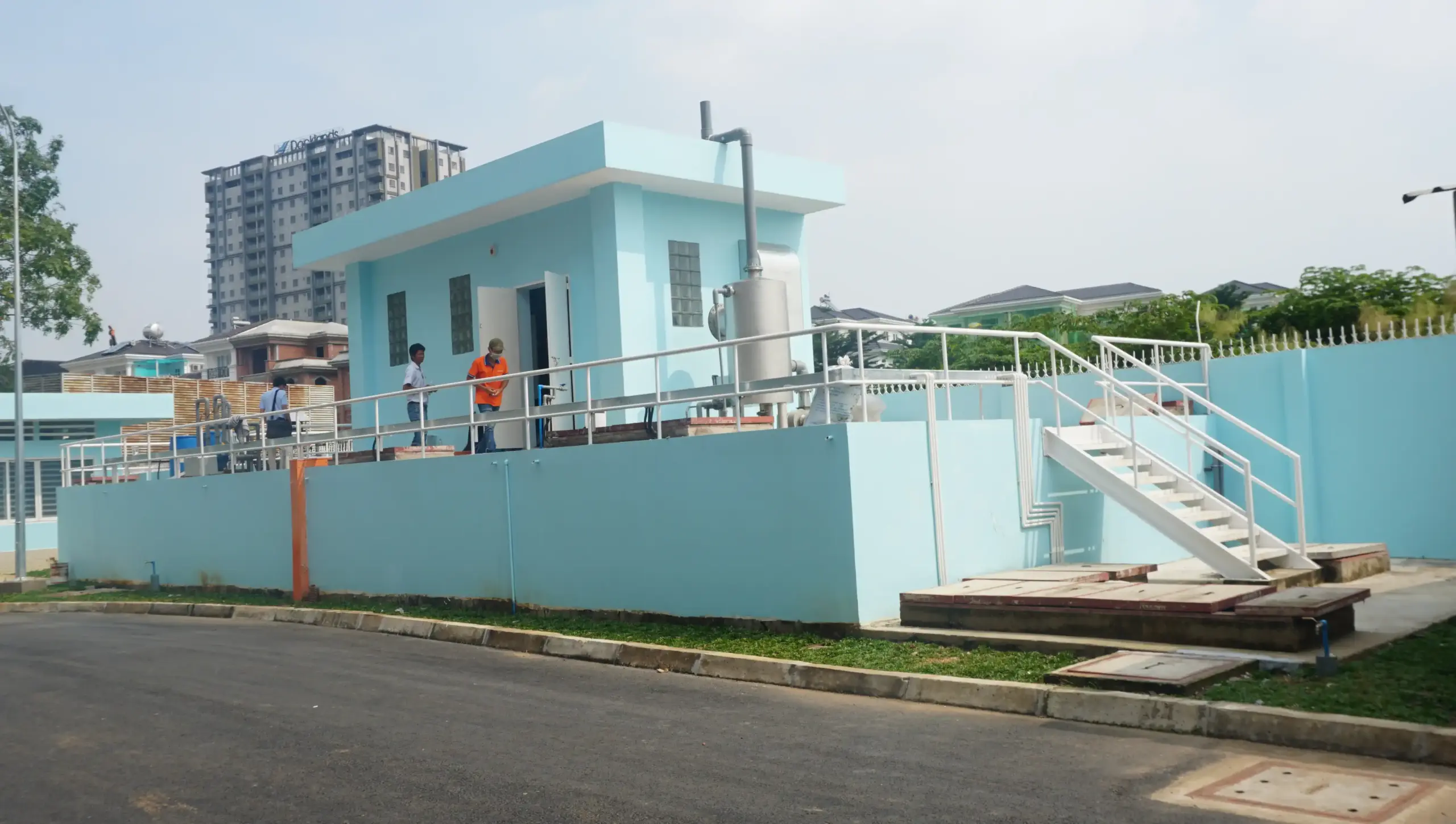
2. Applying a 3D BIM Revit model in system design
One of the key points of the project is that all the equipment and the process piping network were modelled in Autodesk Revit before actual construction began.
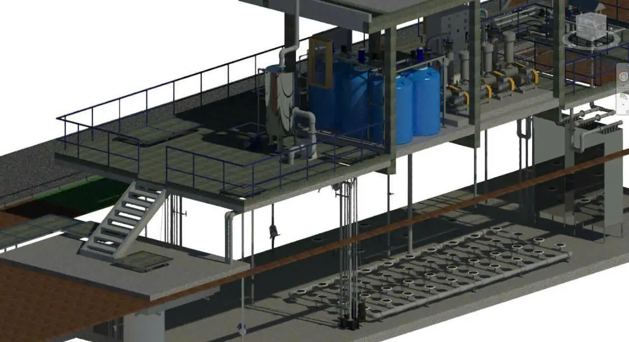
At the plant, equipment density is very high and 4 functional piping systems coexist. With traditional 2D drawings alone, controlling elevations and crossing points would be very difficult.
The 3D BIM Revit model allows the engineering team to check and optimize the following in advance:
- The exact position and elevation of each pipe run.
- Resolution of crossings between the water, air, sludge and chemical lines.
- Placement of pumps and blowers, and the installation space for the MBR membrane modules.
- Adequate clearance for valve operation, equipment access routes and space for dismantling and maintenance.
- Accurate identification of floor penetrations, wall penetrations and pipe supports.
From the completed BIM model, the system goes on to produce shop drawings used directly for on-site installation, thoroughly resolving issues that would otherwise arise before construction.
3. MBR membrane technology – biological treatment combined with membrane filtration
At the heart of the treatment line is the MBR (Membrane Bioreactor) tank. After equalization and biological treatment (anaerobic, anoxic, aerobic), the wastewater is fed into the MBR tank. There, the membranes separate the water from the biological sludge mixture before it passes to disinfection.
| Criteria | Conventional biological settling | MBR membrane filtration (implemented by NTS) |
|---|---|---|
| Sludge separation method | Gravity separation in a secondary clarifier | Direct filtration using hollow-fiber/flat-sheet membranes |
| Construction footprint | Requires large areas for clarifiers and rough filtration tanks | Saves space, with everything organized in a single compact line |
| Effluent quality | Depends on the settleability of the activated sludge | High-quality effluent, removing most bacteria and suspended solids |
The MBR system in this project is fully integrated with membrane suction pumps, membrane cleaning pumps, a membrane aeration system, a membrane cleaning chemical system and flow measuring devices. The design therefore has to address hydraulics, membrane scouring air volume, the suction-cleaning cycle and maintenance access to the modules at the same time.
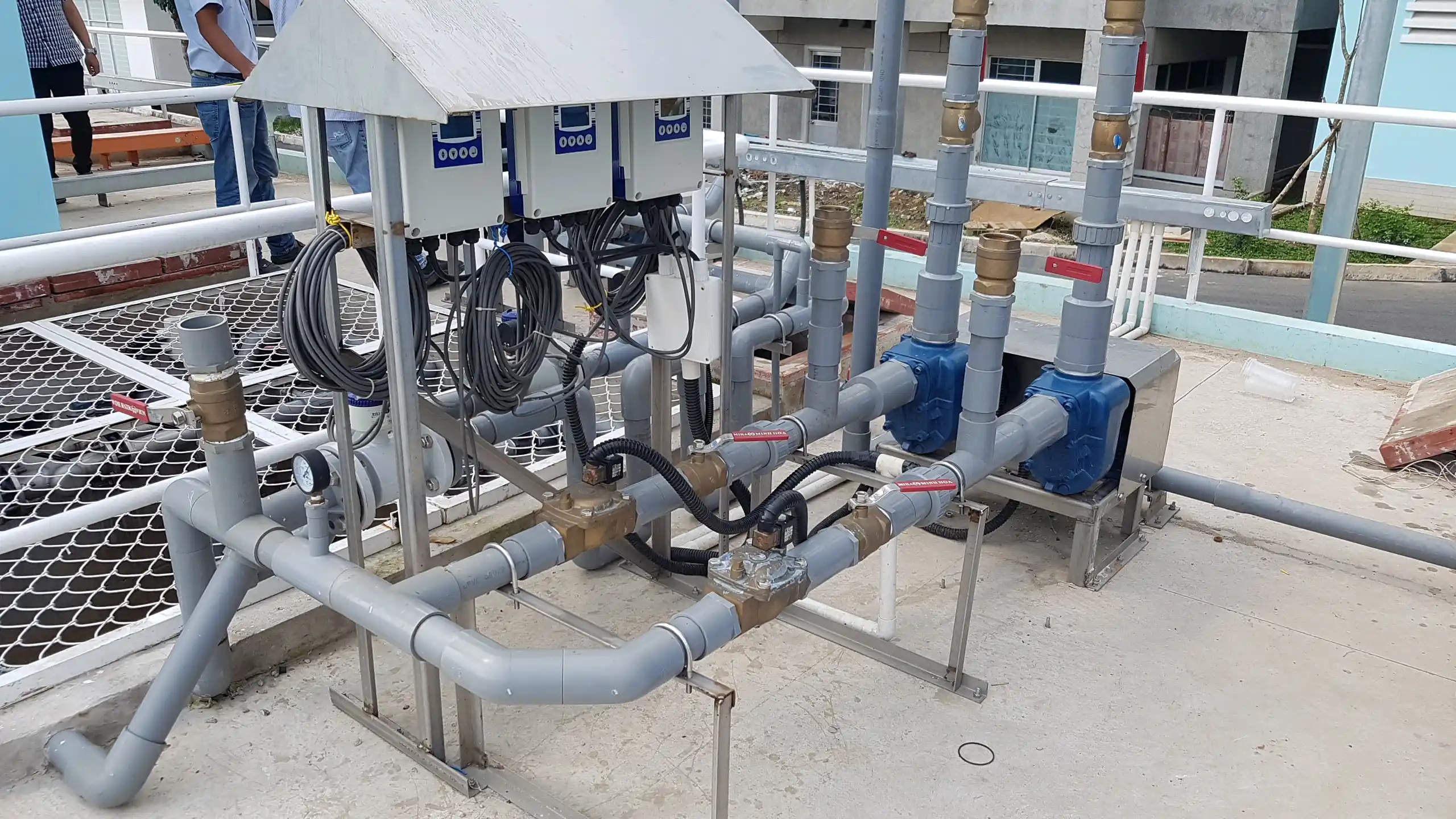
4. Classification of the 4 functional piping networks in the plant
One of the most complex parts of Revit implementation and construction is the process piping network. The whole plant includes 4 main groups of lines:
- Water lines: Convey wastewater through the treatment tanks and the clean water after filtration.
- Sludge lines: Recirculate activated sludge and convey excess sludge to the sludge holding tank.
- Air lines: Supply air to the aerobic tank and for scouring the MBR membranes.
- Chemical lines: Dose disinfection chemicals and MBR membrane cleaning chemicals.
Each piping system has its own requirements for material, elevation, flow velocity and layout. The BIM model coordinates these lines into a single unified whole, completely eliminating the risk of spatial clashes.
5. Equipment layout oriented toward operation and maintenance
Equipment in a hospital wastewater treatment plant must run continuously in a harsh environment. When laying out the 3D space, NTS Engineering paid particular attention to controlling the actual operating clearances:
- Ability to hoist and lift pumps during maintenance.
- Plans for dismantling and lifting the MBR membrane modules out of the tank.
- Clearance for manual valve opening/closing and maintenance access around the blowers.
- Ability to remove individual pipe sections separately during repairs.
6. Plant automation with a PLC system
The system integrates a central control cabinet using a PLC, which automatically manages the pumps, blowers and process equipment according to the programmed logic.
For the MBR system, automation plays a core role in precisely controlling the cycles: membrane suction → aeration → relaxation → backwash → chemical dosing. This minimizes manual operations and ensures equipment service life.
7. Construction and acceptance process for the wastewater treatment plant
Implementation process from drawings to technology transfer
-
1
Construction and installation per shop drawings
Install equipment (pumps, blowers, MBR), the 4-function piping system, valves, supports and the PLC control cabinet based on drawings exported from the BIM model.
-
2
Individual and interlocked test runs (Commissioning)
Check rotation direction, flow rate and pressure of pumps and blowers, pipe tightness, sensor signals and the consistency of the PLC control logic.
-
3
Biomass cultivation and trial operation
Seed the activated sludge and adjust flow, air supply and chemicals so the sludge acclimatizes to the actual wastewater and the system reaches a stable state.
-
4
Water quality monitoring and optimization
Sample and analyze effluent parameters and fine-tune operating settings (membrane suction/cleaning time, recirculated sludge volume) to meet regulatory standards.
-
5
Technology transfer and operator training
Guide the hospital’s technical team to understand the process diagram, PLC cabinet operating procedures, chemical checks and troubleshooting.
Important notes when operating an MBR system
- Always monitor the transmembrane pressure (TMP) to determine when chemical cleaning is needed.
- Ensure continuous aeration in the MBR tank to avoid membrane clogging caused by sludge accumulation.
- Periodically check the mixed liquor suspended solids (MLSS) concentration in the biological tank to maintain optimal treatment performance.
Conclusion
The 300 m³/day hospital wastewater treatment plant project demonstrates NTS Engineering’s comprehensive delivery capability, from process design and the application of 3D BIM Revit, through construction and installation and commissioning, to technology transfer. Mastery of the BIM model improves construction quality, saves cost and ensures the sustainable operation of the facility.


Other Technical Articles
 Advanced
Design and Construction of an Automatic Irrigation System for a Large-Scale Eco-Urban Area
Designing and building an automatic irrigation system for a large-scale eco-urban area of 1.83 million m² demands sophisticated...
Read Article Advanced
Design and Construction of a Large-Scale Performance Pool Technology System Using BIM Revit
Design and construction of a large-scale performance pool technology system using BIM Revit is one of the water...
Read Article Advanced
Design and Construction of Technology Systems for a Large-Scale Complex of 3 Swimming Pools
Designing and building the technology systems for a large-scale complex of three swimming pools (competition, training and children’s)...
Read Article