
Design and Construction of a Large-Scale Performance Pool Technology System Using BIM Revit
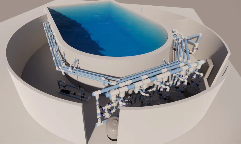
Unlike a conventional swimming pool, this water basin is built directly into the stage area of a large-scale multi-purpose performance complex. The system therefore has to do more than keep the water clean and stable: it must be closely coordinated with the structure, the stage mechanical systems, electrical works, the Chiller and many other MEP systems.

The water volume of the pool system exceeds 1,000 m³. In the technical calculation documents, the volume used to design the filtration system is 1,058 m³; the finalized operation manual records a total pool system volume of approximately 1,400 m³.
Design starts from the operating problem, not from equipment selection
For a system of this size, it is not enough to simply choose one large pump and one large filter and connect them with pipes.
First, it is necessary to determine:
how long the water must take to circulate → what flow rate is needed → how many filtration units to divide into → how the piping is routed → where the equipment is placed → how the system will be operated and maintained.
According to the design basis, the entire water volume must pass through the filtration and disinfection system within approximately 4 hours.
With a calculated volume of 1,058 m³:
Required flow rate ≈ 264.5 m³/h.
The final solution uses 05 pump–filter units, each operating at approximately 54 m³/h, for a total treatment capacity of about:
270 m³/h – equivalent to 270,000 liters of water per hour.
This figure shows the scale of the system quite clearly.
The entire system is designed in 3D with BIM Revit
One of the most important parts of the project was modeling the entire system in Autodesk Revit before construction began.
The assemblies:
pumps – filters – valves – suction header – discharge header – UV – chemicals – heating – piping around the pool
were all built in 3D space.
The goal was not just to produce attractive images.
The Revit model was used to accurately check:
- the elevation of each pipe run;
- crossings between systems;
- clashes with beams and structure;
- equipment installation positions;
- valve operating clearances;
- pump removal space;
- filter maintenance clearances;
- feasibility of actual implementation on site.
In a plant room with a high equipment density and many large-diameter pipe runs at different elevations, resolving these issues in the model before construction significantly reduces the need to reroute pipes on site.
From the BIM model, the design team went on to develop shop drawings to be used directly for construction.
05 filtration modules operating in parallel
Instead of relying on a single very large filtration unit, the system is divided into 05 independent modules.
Each module consists of:
pump → valve set → sand filter → pressure monitoring.
The system uses 05 filter pumps, each with a flow rate of approximately 54 m³/h and a head of approximately 18.5 m.
These are paired with 05 pressure filters approximately 1,400 mm in diameter, using quartz sand as the filter media.
This modular arrangement makes the system more flexible for:
operation – backwashing – equipment isolation – maintenance – repair.
If one unit needs to be inspected, the entire system does not have to be shut down.
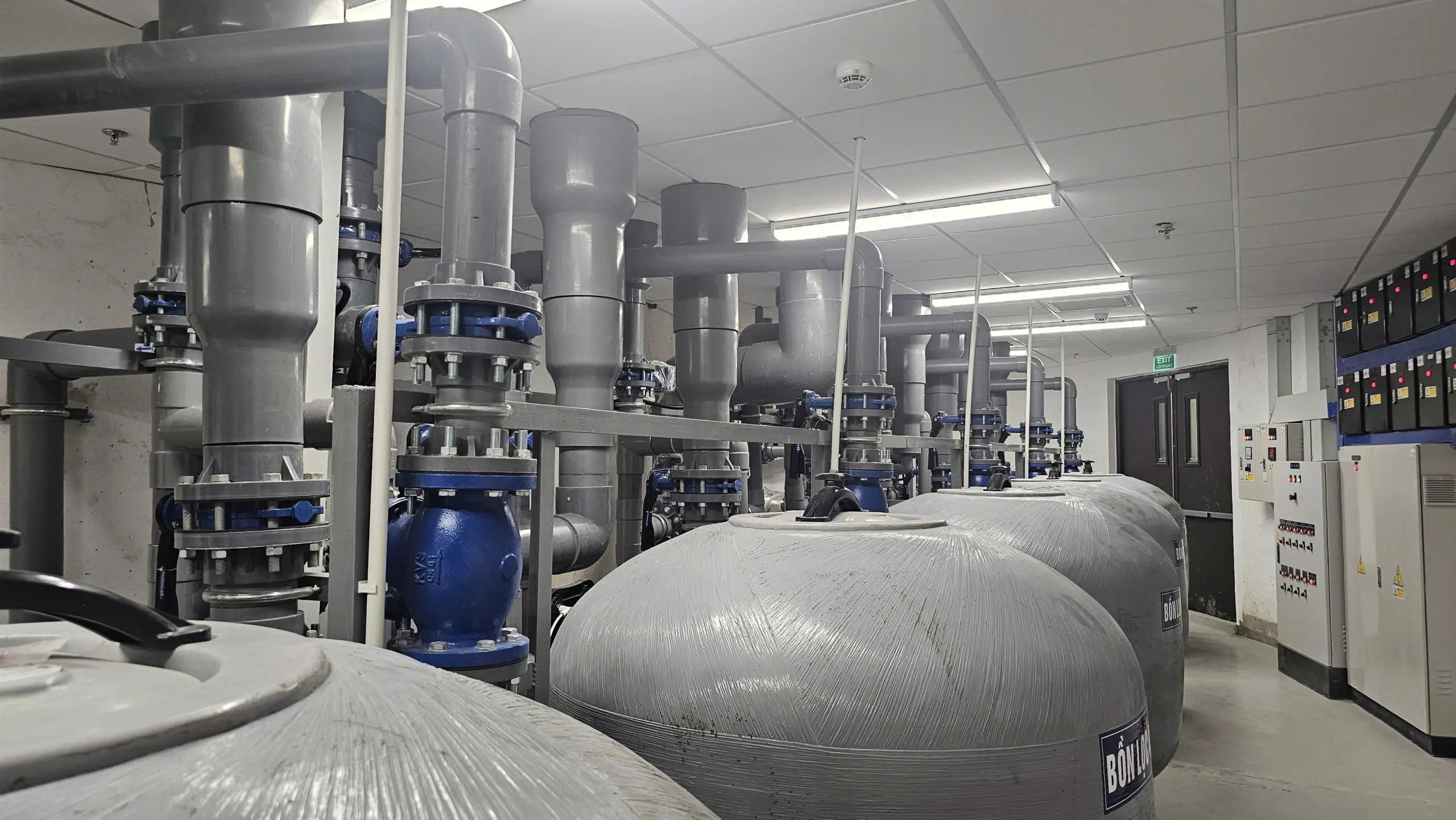
30 motorized valves and a PLC controlling the filtration process
One clear difference from a small swimming pool plant room is that the system does not use manually operated multiport valves.
Each filter is fitted with 06 motorized valves.
With 05 filters:
05 × 06 = 30 motorized valves
for the filtration system alone.
The PLC controls the valves to automatically carry out the main modes:
FILTER – normal filtration
BACKWASH – reverse washing
RINSE – rinsing after Backwash
CLOSED – filter isolation.
The key point is that the PLC does not allow the pump to start immediately.
The sequence is controlled:
stop pump → switch valves → confirm valve status → only then allow the pump to run.
This interlock logic helps prevent the pump from running while the water line is closed or the valves have not completed their full travel.
Filters perform Backwash and Rinse automatically
After a period of operation, debris retained in the sand bed increases the pressure loss across the filter.
The system monitors the pressure at each filtration unit. When cleaning is needed, the PLC runs the following cycle:
stop pump → switch valves to Backwash → reverse-wash the sand bed → stop pump → switch to Rinse → rinse → return to Filter mode.
Backwash typically lasts about 3–5 minutes, followed by Rinse for about 1–2 minutes to resettle the filter media before the water is returned to the pool.
As a result, filter cleaning is standardized into a defined procedure rather than depending entirely on operator actions.
Not just removing debris: the water also receives UV treatment and automatic chemical control
The treatment train is organized according to the following principle:
Pool → water collection → pump → sand filtration → UV → chemical control → heating → water returned to the pool.After mechanical impurities are removed, the water continues through a UV system with a capacity of approximately 300 m³/h, sufficient to handle the entire circulation flow of the system.
Alongside the UV is an automatic water quality controller.
Sensors continuously monitor:
pH and ORP
after which the controller commands the dosing pumps to add chemicals according to actual water quality.
The operating range is set at approximately:
pH: 7.2–7.6
ORP: 750–850 mV.
In this way, the system does not merely make the water “look clear” but also controls the parameters related to water quality and disinfection capability.
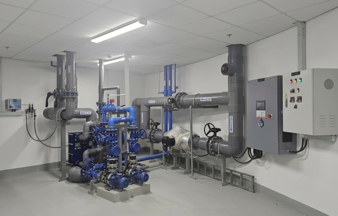
Water heating for performance activities
Because performers work directly in the water, temperature is also part of the technology problem.
The design includes a heat exchanger with a capacity of approximately 200 kW, aiming to raise the water temperature from about:
22°C → 26°C.
The heating system is coordinated with the building’s Chiller system rather than operating as an independent system.
This also shows that the pool technology system must be designed within the overall MEP of the entire building and cannot be treated separately.
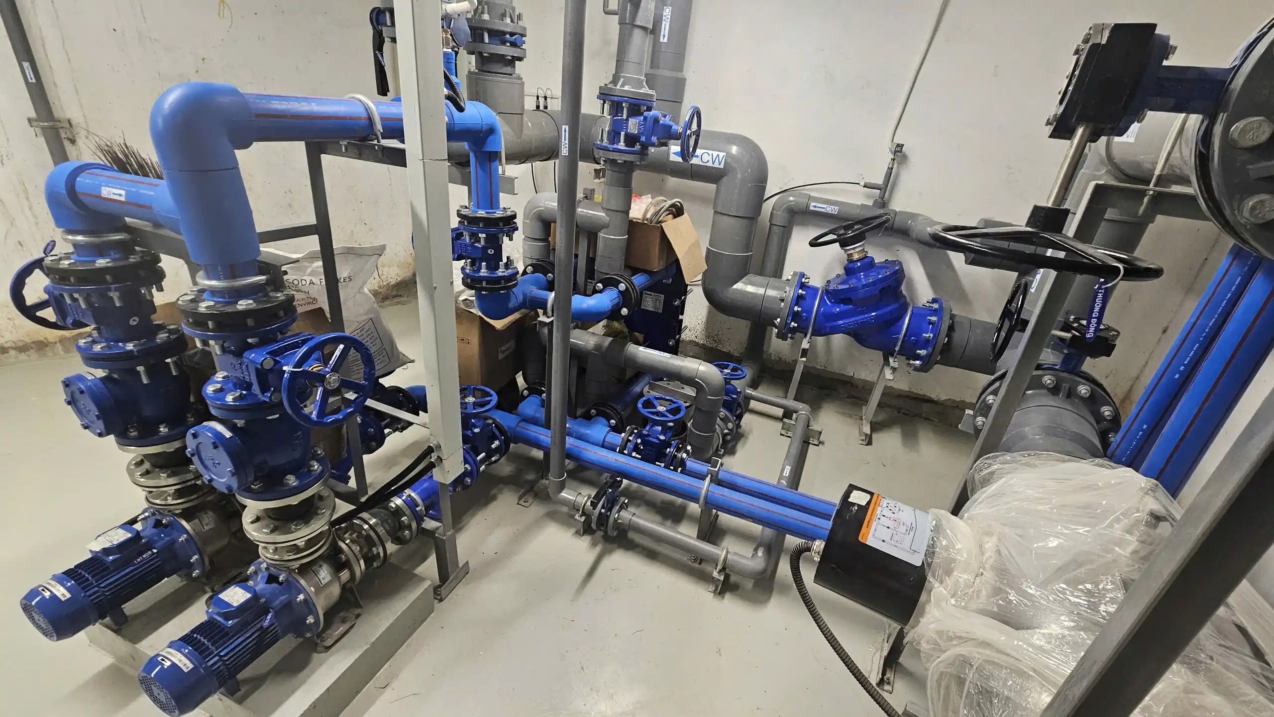
A 350 m³ storage tank saves water during maintenance
A rather distinctive solution in this project is a storage tank of approximately 350 m³ for operation and maintenance purposes.
When the pool water level needs to be lowered, part of the water can be pumped to the storage tank instead of being discharged completely.
After the work is finished, the water can be pumped back into the pool.
This solution helps to:
- reduce the amount of water that must be discharged;
- reduce the time needed to refill the water;
- reduce the amount of chemicals that must be treated again;
- shorten the time needed to bring the system back into operation.
The water transfer is carried out by a dedicated pump combined with motorized valve sets and water level signals to protect against the tank being full or empty.
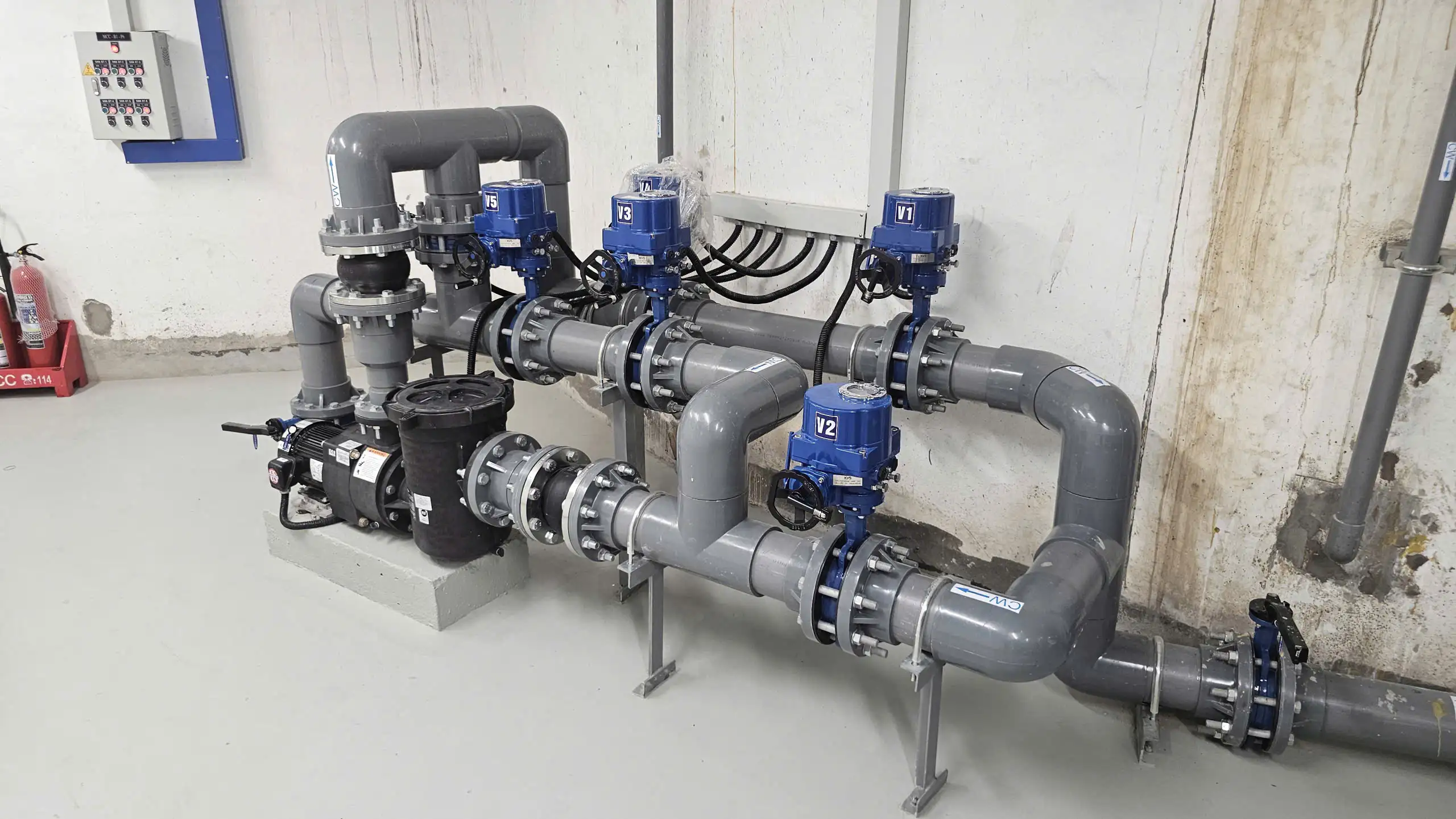
Construction must start at the structural stage
A system of this scale cannot wait until the pool is finished before pipe installation begins.
Many pipe runs must be positioned before the concrete is poured.
The runs passing through slabs and walls and the bottom drains are large in size, including pipes up to DN315.
Project implementation sequence
- 1
BIM Revit 3D
Process design, hydraulic calculation and 3D modeling of the entire system.
- 2
Shop Drawing & Embedded Pipework
MEP coordination, shop drawing development, positioning of sleeves/pipe stubs and installation of embedded pipework before concrete pouring (acceptance + pressure testing).
- 3
Plant Room Equipment Installation
Completion of the plant room and installation of the pump units, filters, UV, chemical systems and heat exchanger.
- 4
PLC Automation & Commissioning
Electrical connection, PLC control programming and test runs according to the standard cycle.
- 5
Operational Handover
Handover of technical documents and operation manuals, and training for the management team.
This is also where the 3D model delivers real value: clashes resolved on the computer in advance significantly reduce chiseling and rework, pipe changes, or waterproofing repairs on site.
From 3D model to a real operating system
Once completed, the system is commissioned stage by stage before synchronized operation.
The Filter, Backwash and Rinse modes are tested; the pumps, pressure, UV, chemical system, heating and PLC logic are all test-run before handover.
The operating team is then given specific instruction on:
start-up – operation – filter washing – water quality control – troubleshooting – equipment maintenance.
The handover package also includes separate operation documents for the pumps, filters, UV, chemical system, electrical cabinets, valve cabinets and heat exchanger.
The value of an integrated system design
What is notable about the project lies not only in figures such as:
over 1,000 m³ of water – 270 m³/h filtration flow – 05 pumps – 05 filters – 30 motorized valves – UV 300 m³/h.
The greater value lies in how the entire system was delivered:
Process design → hydraulic calculation → BIM Revit 3D → MEP coordination → Shop Drawing → construction → PLC automation → Commissioning → operational handover.
Key considerations when designing large-scale water technology
- A good design must not only be correct in its calculations but also buildable, stable in operation, easy to maintain and controllable throughout the life of the facility.
- Start from the real operating problem instead of rushing to select equipment.
- Thoroughly resolve spatial clashes in BIM Revit 3D before going to site, to avoid chiseling and rework of the structure.
Conclusion
This is also how we approach swimming pool projects, performance pools and large-scale water circulation and treatment systems with demanding technical requirements. NTS Engineering is committed to delivering the most comprehensive, integrated and optimal solution for every project.


Other Technical Articles
 Advanced
Design and Construction of an Automatic Irrigation System for a Large-Scale Eco-Urban Area
Designing and building an automatic irrigation system for a large-scale eco-urban area of 1.83 million m² demands sophisticated...
Read Article Advanced
BIM Revit Design and Construction of a District 7 Hospital Wastewater Treatment System – 300 m³/day
This 300 m³/day hospital wastewater treatment plant was delivered by NTS Engineering on a turnkey basis, from process...
Read Article Advanced
Design and Construction of Technology Systems for a Large-Scale Complex of 3 Swimming Pools
Designing and building the technology systems for a large-scale complex of three swimming pools (competition, training and children’s)...
Read Article